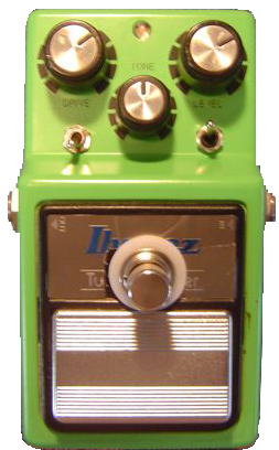
Taking apart the TS-9 is straightforward. There are four screws on the bottom, plus 2 more inside to remove. Then, tackle the pots and jacks. For each of these pictures, you can get a super close-up, high resolution view by double-clicking on the photo.
STEP 1: Remove the Screws
 Remove the 4 screws on back; pull out the battery compartment top to expose 2 more hidden screws. Remove the back plate and the black plastic insulator sitting between the backplate and the circuit board. Remove the 4 screws on back; pull out the battery compartment top to expose 2 more hidden screws. Remove the back plate and the black plastic insulator sitting between the backplate and the circuit board.
Make sure to save all the screws and especially the insulator!
Once you have the insulator off, remove the single ground screw at the upper left which holds the circuit board in place.
|
|
STEP 2: Remove the Nuts
 Remove the 3 plastic knobs by just pulling upward. Remove the 3 nuts holding the potentiometers in place. Remove the 3 plastic knobs by just pulling upward. Remove the 3 nuts holding the potentiometers in place.
Remove the input and output jack nuts on the sides of the unit.
This will completely free the circuit board, pots and jacks. The only 2 wires left to the footswitch - you can remove these if you want (I chose not too) -- it will make it easier to work on. If you do choose to remove them, unsolder the connections and write down the colors of the wires to each terminal.
| |
STEP 3: Remove the LED PCB
 Pull up on the main PCB to expose the potentiometers and LED PCB. The LED PCB is held in place by a single screw. Pull up on the main PCB to expose the potentiometers and LED PCB. The LED PCB is held in place by a single screw.
Once you get this screw out, you can pull out the PCB and then pull apart and separate the main PCB and potentiometer wiring harness from the unit. | |
 Here is the Main PCB and the pots and their harness. You might want to write down the colors of the wires for the harness and the potentiometer names (gain, tone, level). Here is the Main PCB and the pots and their harness. You might want to write down the colors of the wires for the harness and the potentiometer names (gain, tone, level).
You will be moving the PCB board around quite a bit and it will not be uncommon for a harness wire to break on you. For this reason, it might be worth the effort to take a picture or make a schematic of the harness.
|
|


No comments:
Post a Comment