

The Distortion Mod might be the most complex from the standpoint of the wiring. Getting the diode wiring can be tricky. I decided to wire mine so that I could change all the diodes without having to mess with the circuit board. You might choose to do it differently after you check the schematic. This mod gives the distortion a bright, British character and sounds like a different distortion box altogether. Pair it with the Bass Boost mod and you get yet another channel sound!
The Schematic Here's the schematic for this mod. The two distortion diodes are both 1N914 variety. One diode clips the upper portion of the input signal, the other the lower portion. By replacing the other diode with 3 diodes in series, it drastically changes the threshold for clipping for one side. This creates an asymmetry in the signal that is a completely different kind of sound than the traditional Tube Screamer. Here's the schematic for this mod. The two distortion diodes are both 1N914 variety. One diode clips the upper portion of the input signal, the other the lower portion. By replacing the other diode with 3 diodes in series, it drastically changes the threshold for clipping for one side. This creates an asymmetry in the signal that is a completely different kind of sound than the traditional Tube Screamer. | |
STEP 1: Remove and Re-Route the Diodes  The first thing I did was remove the two 1N914 diodes which are right next to the op amp. Click on the picture to enlarge it. I wired red wires into one side and black wires to the other side right through the component holes. By doing this and relocating the diodes to be near the switch, it saves time and complexity and makes it easier to modify the mod in the future. The first thing I did was remove the two 1N914 diodes which are right next to the op amp. Click on the picture to enlarge it. I wired red wires into one side and black wires to the other side right through the component holes. By doing this and relocating the diodes to be near the switch, it saves time and complexity and makes it easier to modify the mod in the future. | |
STEP 2: Prep the Diodes  You can find 1N914 diodes easily. There is nothing inherent in the original parts that is magic, but if you really want to re-use them, feel free to do so. You can find 1N914 diodes easily. There is nothing inherent in the original parts that is magic, but if you really want to re-use them, feel free to do so.Here, I have prepped the 3-diodes in series, connected to a single diode. The switch will choose either the 3 in series, or the single diode and this is how the mod functions. | |
STEP 3: Wire the Diodes and Switch  Here you can see how I have wired the DPDT switch. One side handles the negative side (3 or 1 diodes) the other handles the positive side. In this case, the positive side gets 1 diode either way so that is a bit redundant. But, if I decide to change the mod later it will be much easier now. Here you can see how I have wired the DPDT switch. One side handles the negative side (3 or 1 diodes) the other handles the positive side. In this case, the positive side gets 1 diode either way so that is a bit redundant. But, if I decide to change the mod later it will be much easier now. | |
 Now connect the switch/diode combo to the black and red wires from Step 1. The red wires go to the center poles, while the black wires connect the other ends of the diode assemblies. Now connect the switch/diode combo to the black and red wires from Step 1. The red wires go to the center poles, while the black wires connect the other ends of the diode assemblies. | |
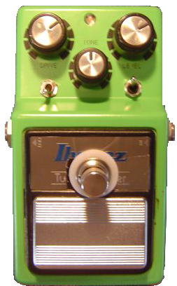
STEP 4: Mount the Switch  As with the other mods, make this the last step. Here you can see the distortion switch mounted just under the Drive knob. As with the other mods, make this the last step. Here you can see the distortion switch mounted just under the Drive knob.You can also see the rest of the mods in place. To test, plug and play. The distortion sound is drastically different so you will definitely be able to hear it. If not, check your wiring. |


What are the black components wired to the end of the diodes in STEP 3, second picture. Also, is that heat shrink wrap on the diodes in that picture? Thanks.
ReplyDelete